
An automotive air conditioning (AC) system is a closed-loop vapour compression refrigeration circuit that removes heat and humidity from cabin air by cycling a refrigerant through four primary state changes: compression, condensation, expansion, and evaporation. These changes are driven by engine or motor power.
According to Tom Birch’s Automotive Air Conditioning and Heating (Pearson, 8th edition), the thermodynamic principle at work is identical to that of a household refrigerator: the system does not ‘produce cold’, but instead continuously relocates thermal energy from inside the passenger compartment to the outside atmosphere. SAE International’s technical standard J639 (Safety Standards for Motor Vehicle Refrigerant Vapor Compression Systems) establishes the performance benchmarks and refrigerant handling protocols that modern original equipment manufacturer (OEM) AC system design must meet. This includes the industry-wide transition from R-134a to R-1234yf, which is driven by global low global warming potential (GWP) mandates.
The Engineering Logic Behind Cabin Cooling
Most drivers use their car’s air conditioning system without considering how its design departs from intuitive assumptions. The most significant misconception is that an air conditioner generates cold air, which it does not do. What the system does is direct the movement of thermal energy: the heat inside the vehicle is absorbed by a refrigerant, transported outside the passenger compartment, and released into the surrounding air through a heat exchanger at the front of the vehicle. The cabin feels cooler not because cold air has been introduced, but because heat has been systematically extracted.
This distinction is important because it explains every design decision in the system’s architecture. The refrigerant — R-134a in vehicles manufactured before around 2014–2017 and R-1234yf in most vehicles produced since 2017 — is the working fluid that enables this thermal migration. Its value lies in a specific thermodynamic property: it undergoes phase changes (from liquid to gas and back again) at pressures that can be achieved using a belt-driven or electrically powered compressor. These phase changes absorb or release substantial quantities of latent heat. The entire mechanical system exists to control where and when these phase changes occur, ensuring that heat is absorbed inside the vehicle and rejected outside it.
A second important principle is that the automotive AC system is simultaneously a dehumidification system. As warm cabin air passes over the evaporator core — which is cold enough that its surface temperature drops below the dew point of the incoming air — moisture condenses on the evaporator fins and drains out of the vehicle through a condensate drain port. This is why the pavement under a parked car with the AC running shows a puddle of clean water; it is not a leak, but condensed humidity removed from the cabin atmosphere. The combined effect of temperature reduction and dehumidification is why automotive AC system performance is measured by both dry-bulb temperature drop and wet-bulb outlet conditions in SAE J639 testing protocols.
The Core Components and Their Functions
The automotive AC system comprises five primary components, each performing a specific thermodynamic role within the vapor-compression cycle. Understanding what each component does — and why — provides the foundation for diagnosing failures, evaluating refrigerant charge levels, and understanding why aftermarket modifications to one component invariably affect system-wide performance.
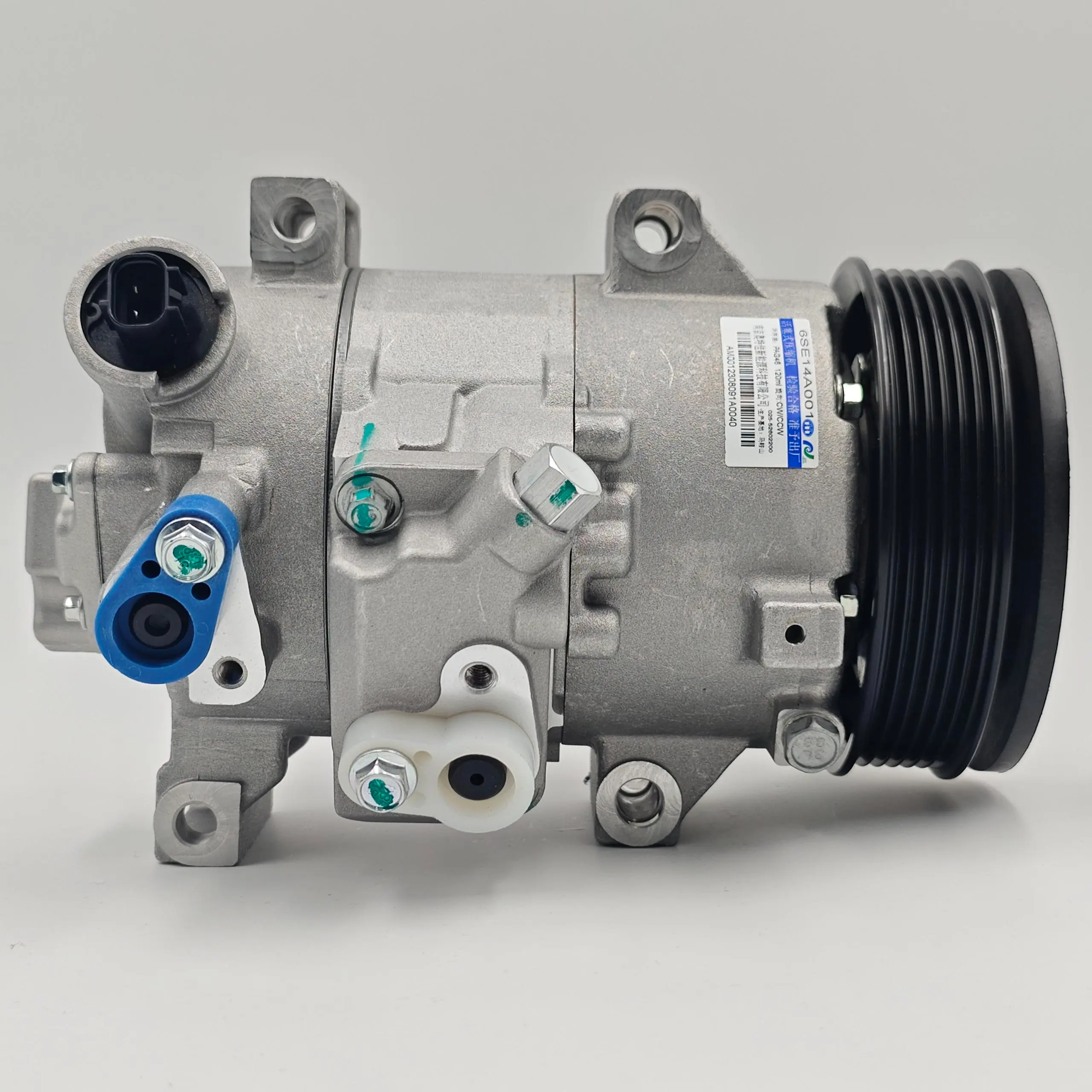
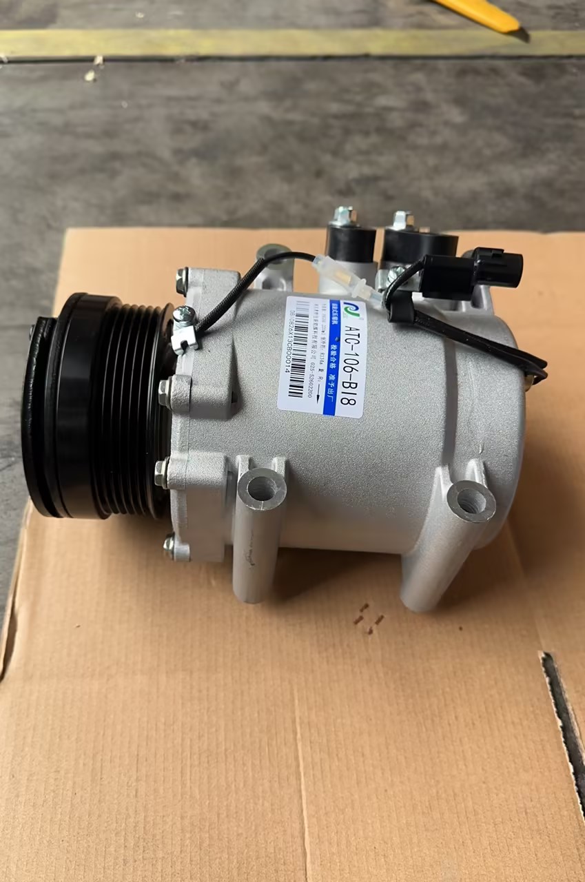
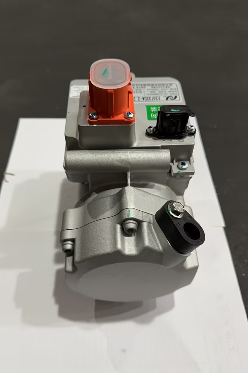
The compressor is the pressure-building heart of the system. In belt-driven configurations, an electromagnetic clutch engages the compressor pulley when the AC is switched on, drawing rotational energy from the engine’s accessory drive belt. In modern hybrid and battery electric vehicles, the compressor is an electrically driven hermetic unit, entirely decoupled from combustion engine RPM. The compressor takes low-pressure refrigerant vapor from the evaporator outlet and compresses it into a high-pressure, high-temperature vapor — creating the pressure differential that drives the entire refrigerant circuit. Variable displacement compressors, which have become predominant in OEM applications since the mid-2000s, continuously modulate their swept volume to match the thermal load of the cabin, reducing parasitic engine losses and improving fuel economy compared to earlier fixed-displacement designs.
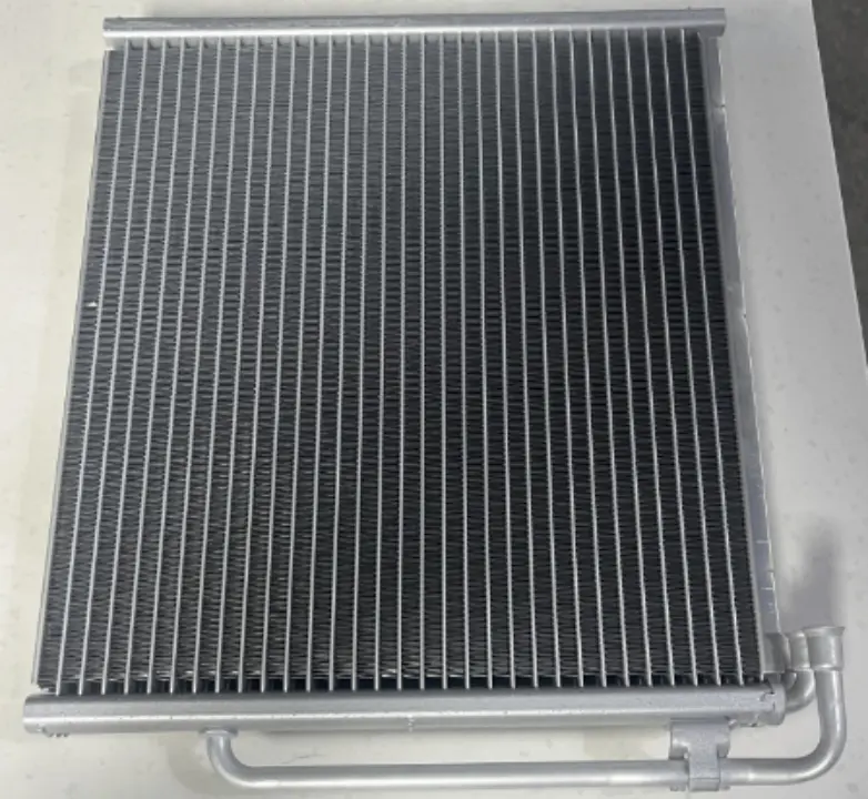
The condenser is a fin-and-tube heat exchanger positioned directly behind the front grille, where it is exposed to the highest available ambient airflow. Hot, high-pressure refrigerant vapor from the compressor outlet flows through the condenser, where it surrenders its heat to the passing airstream and condenses back into a liquid. Condenser cooling is supplemented by one or more electric radiator fans that activate when vehicle speed is insufficient to produce adequate airflow — a critical function during idle or low-speed operation in high-ambient-temperature conditions, where condenser outlet temperature directly limits system performance.
The receiver-drier (in orifice tube systems, an accumulator) serves as a liquid reservoir, moisture trap, and filter between the condenser and the expansion device. It contains a desiccant — typically silica gel or molecular sieve material — that absorbs residual moisture from the refrigerant circuit. Moisture in a refrigerant circuit is not merely undesirable; it reacts chemically with R-134a and PAG compressor oil to form hydrochloric and hydrofluoric acids, which corrode aluminum components and degrade compressor seal materials. The receiver-drier’s desiccant has a finite capacity and must be replaced when the system is opened for service.
The expansion device — either a thermal expansion valve (TXV) or a fixed orifice tube — is where the high-pressure liquid refrigerant undergoes a sudden pressure drop, entering the evaporator as a low-pressure, partially vaporized mixture at temperatures typically between −4°F and 14°F (−20°C to −10°C). The TXV uses a temperature-sensing bulb at the evaporator outlet to modulate refrigerant flow dynamically in response to load changes; the simpler fixed orifice tube relies on the accumulator and cycling of the compressor clutch to regulate evaporator conditions.
The evaporator is the component that performs the actual cooling of cabin air. Positioned inside the HVAC plenum box — typically behind the dashboard — it is a compact fin-and-tube heat exchanger through which the cold, low-pressure refrigerant absorbs heat from recirculated or fresh cabin air blown across it by the blower motor. As the refrigerant absorbs heat, it fully vaporizes, and this vapor returns to the compressor inlet to complete the cycle.
Automotive AC System: Component Reference Table
| Compressor | Engine bay, belt-driven or electric | Pressurize refrigerant vapor | No cooling; loud knocking; clutch not engaging |
| Condenser | Front of vehicle, behind grille | Reject heat to atmosphere | Reduced cooling; high head pressure |
| Receiver-Drier / Accumulator | Between condenser & expansion valve | Filter, dry, and store refrigerant | Moisture contamination; desiccant saturation |
| TXV / Orifice Tube | Evaporator inlet | Reduce pressure, meter flow | Freeze-up; erratic cooling; low suction pressure |
| Evaporator | HVAC plenum, behind dashboard | Absorb cabin heat into refrigerant | Warm air; frost buildup; musty odor |
| Blower Motor | HVAC box | Circulate air across evaporator | No airflow; noise; single-speed operation only |
| Pressure Switches (H/L) | High and low side lines | Protect compressor from over/under-pressure | Compressor cycling off; AC inoperative |
The Refrigeration Cycle: How Heat Is Transferred
The vapor-compression refrigeration cycle that governs automotive AC system operation proceeds through four thermodynamically distinct stages, each corresponding to a physical region of the refrigerant circuit. Understanding the cycle as a continuous, pressure-driven loop — rather than as a sequence of isolated events — is essential for accurate pressure testing and system diagnosis.
Stage 1 — Compression (Compressor): Low-pressure refrigerant vapor, which has absorbed heat in the evaporator, enters the compressor at approximately 25–35 psi (R-134a at typical ambient conditions). The compressor raises this to 150–275 psi on the high side, simultaneously raising the refrigerant’s temperature to 150–180°F (65–82°C). This high-energy state is what enables the condenser to reject heat against an ambient temperature that could itself be 90–100°F — the pressure increase creates the temperature differential needed for heat to flow in the right direction.
Stage 2 — Condensation (Condenser): The hot, high-pressure vapor flows through the condenser, where it loses heat to the ambient airstream. As the vapor cools below its condensation point (at high-side pressure), it transitions to liquid. This phase change releases a large quantity of latent heat — approximately 85–95 BTU/lb for R-134a — into the atmosphere. The refrigerant exits the condenser as a warm, high-pressure liquid.
Stage 3 — Expansion (TXV or Orifice Tube): The high-pressure liquid passes through the expansion device, where a controlled restriction causes a sudden pressure drop to approximately 15–30 psi. This flash expansion causes partial vaporization and drops the refrigerant temperature to well below the freezing point of water. The mixed liquid-vapor refrigerant entering the evaporator is the coldest substance in the system.
Stage 4 — Evaporation (Evaporator): Inside the evaporator, the cold refrigerant mixture absorbs heat from warm cabin air blown across the fins. This heat absorption drives the remaining liquid refrigerant to vaporize completely — again, a latent heat process, absorbing approximately 85–95 BTU/lb from the airstream without changing the refrigerant’s own temperature until fully vaporized. The now-warm, low-pressure vapor returns to the compressor inlet, and the cycle repeats continuously for as long as the compressor runs.
This four-stage cycle explains why a properly functioning automotive AC system can achieve a 30–40°F (17–22°C) temperature differential between ambient outside air and the air delivered to the cabin vents under standard SAE J639 test conditions.
The Electrical and Control Architecture
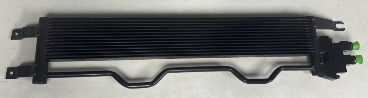
Modern automotive air conditioning (AC) systems are not purely mechanical; they are deeply integrated into the vehicle’s electronic control architecture. Compressor operation, blower speed, mode door positioning and temperature targeting are all managed by either a dedicated heating, ventilation and air conditioning (HVAC) control module or the broader body control module (BCM), depending on the vehicle platform.
The high- and low-pressure refrigerant circuits are protected by pressure transducers or switches connected to the HVAC control module. If the high-side pressure exceeds approximately 375–400 psi — a condition that can be caused by a blocked condenser, a failed fan, or an overcharged refrigerant — the system will shut the compressor off to prevent mechanical damage. Conversely, if the low-side pressure drops below 15–20 psi (indicating refrigerant loss), the compressor is disabled again to prevent oil starvation and bearing failure. These protective strategies explain why a system with low refrigerant levels often presents as an AC compressor that cycles on for two to three seconds and then immediately disengages, rather than simply running poorly.
In automatic climate control systems, ambient temperature, in-cabin temperature, solar load, and sometimes humidity sensors feed continuous data to the HVAC module. This adjusts the blower speed, compressor displacement, and blend door angle in real time to maintain the target temperature set by the occupants. In battery electric vehicles (BEVs), this control architecture becomes significantly more complex because there is no waste engine heat available for cabin heating. Consequently, BEV HVAC systems typically incorporate a heat pump cycle — running the refrigerant circuit in reverse to extract heat from the ambient air — as well as a positive-temperature-coefficient (PTC) electric heater as a supplemental source. All of these components are coordinated by the thermal management system to optimise range consumption.
Refrigerant Comparison: R-134a vs. R-1234yf
| Chemical Name | Tetrafluoroethane | 2,3,3,3-Tetrafluoropropene |
| Global Warming Potential (GWP) | 1,430 | 4 |
| Boiling Point (1 atm) | −26.3°C (−15.3°F) | −29.4°C (−21°F) |
| Flammability Class | A1 (non-flammable) | A2L (mildly flammable) |
| Typical System Charge (mid-size sedan) | 500–750 g | 450–700 g |
| Regulatory Status | Phased out in EU new vehicles (2017+); being phased out in NA | Mandated in EU; preferred in most new global platforms |
| Compatible Compressor Oil | PAG (various viscosities) | POE or specific PAG-YF |
| Price per lb (approximate, 2024) | $3–$8 | $30–$50 |
| Cross-Contamination Risk | Not compatible with R-1234yf systems | Requires dedicated equipment; system damage if R-134a used |
The transition from R-134a to R-1234yf is the most significant refrigerant change since the R-12 to R-134a phase-out mandated by the Montreal Protocol. While R-1234yf’s GWP of 4 versus R-134a’s 1,430 represents a dramatic environmental improvement — the driving force behind EU MAC Directive 2006/40/EC and equivalent U.S. EPA SNAP program listings — the mildly flammable A2L classification of R-1234yf introduces handling and equipment requirements that differ from previous automotive refrigerant practice. SAE J2843 governs R-1234yf recovery, recycling, and recharge equipment specifications, and technicians must use J2843-certified machines rather than the J2788-certified equipment used for R-134a.
Common Failure Modes and Diagnostic Logic
The four most common reasons an automotive AC system stops cooling effectively are refrigerant loss, compressor failure, condenser airflow restriction, and expansion device malfunction — and in a well-equipped shop, a set of manifold gauge readings will distinguish between them in under ten minutes.
Refrigerant loss is the most frequent issue in vehicles older than five years. Refrigerant escapes through micro-leaks in O-ring seals at component connections, through Schrader valve cores, through degraded shaft seals on the compressor, or — less commonly — by permeation through hose material. The diagnostic signature is low suction pressure (below 25 psi at idle with 70°F ambient) combined with low discharge pressure (below 150 psi). Adding refrigerant temporarily restores function, but the correct repair is leak detection using UV dye or electronic leak detectors, followed by component or seal replacement.
Compressor failure manifests in several ways depending on failure mode: a seized compressor produces a loud metallic knocking and often causes the drive belt to squeal or snap; a compressor with a failed clutch engages the belt pulley but does not turn the compressor shaft; an internally worn compressor running at reduced displacement produces inadequate high-side pressure (below 120–140 psi at normal operating conditions) despite correct refrigerant charge. Compressor failure frequently contaminates the entire refrigerant circuit with metallic debris and degraded oil, requiring flush of the condenser, replacement of the expansion device, and installation of an in-line filter at the compressor outlet.
Condenser airflow restriction — caused by debris accumulation between the condenser and radiator, insect compaction in the fin surface, or a failed condenser fan — drives high-side pressure to abnormally elevated levels (above 300 psi at moderate ambient temperatures) while suction pressure remains normal. The system cools poorly not because of refrigerant issues, but because the condenser cannot adequately reject heat to the atmosphere.
FAQ: Automotive AC System — Top Search Questions Answered
Q1: Why is my car AC blowing warm air?
The most common causes of warm air from an automotive AC system are low refrigerant charge due to a leak, a failed or disengaged compressor clutch, a blocked condenser reducing heat rejection capacity, or a failed expansion device causing evaporator freeze-up. A manifold gauge set connected to the high and low side service ports will identify which failure mode is present within minutes — low readings on both sides typically indicate refrigerant loss, while high readings on the high side alone point to condenser or fan issues. Attempting to recharge refrigerant without first diagnosing the root cause will temporarily restore cooling but will not address the underlying leak or component fault.
Q2: How often should I recharge my car’s AC system?
A properly functioning automotive AC system sealed at the factory does not require periodic refrigerant recharging. Unlike engine oil, refrigerant does not get consumed or degrade with use — it circulates in a closed loop. If a system requires recharging, it means refrigerant has escaped through a leak, and the correct response is to locate and repair the leak before adding refrigerant. Automotive engineers and SAE standard J639 both specify that a system with no leaks should maintain its original factory charge for the vehicle’s service life. Annual “top-off” services at quick-lube facilities are unnecessary on a properly sealed system and can mask worsening leaks.
Q3: What is the difference between R-134a and R-1234yf refrigerant?
R-134a has a Global Warming Potential (GWP) of 1,430 and has been the standard automotive refrigerant since the early 1990s when R-12 (Freon) was phased out under the Montreal Protocol. R-1234yf, now mandated for new vehicles in the European Union and used in most post-2017 North American production, has a GWP of just 4 — a 99.7% reduction. The two refrigerants are not interchangeable: their system pressures, compatible compressor oils, and service equipment requirements differ, and cross-contaminating a system causes component damage. R-1234yf is classified A2L (mildly flammable), requiring dedicated handling equipment per SAE J2843.
Q4: Why does my car AC smell musty or moldy?
A musty odor from automotive AC vents is caused by microbial growth — primarily mold, mildew, and bacteria — colonizing the wet surface of the evaporator core and the foam lining of the HVAC plenum box. The evaporator is perpetually damp during AC operation because it condenses humidity from the cabin air, creating an ideal growth environment in the dark, enclosed plenum. The recommended maintenance practice is to run the blower on high with the AC compressor off for the final two to three minutes before shutting the vehicle down, allowing the evaporator surface to partially dry. Persistent odor is addressed with antimicrobial evaporator treatment sprays applied via the blower intake duct, or — in severe cases — evaporator removal and cleaning.
Q5: Does running the car AC hurt fuel economy?
Yes — engaging the compressor of an automotive AC system imposes a measurable parasitic load on the engine. The EPA estimates a fuel economy penalty of approximately 5–25% depending on ambient temperature, vehicle size, and driving conditions, with the highest penalties at low vehicle speeds and high ambient temperatures when the compressor runs continuously at maximum load. At highway speeds above 55 mph (88 km/h), the aerodynamic drag penalty of driving with windows open typically exceeds the fuel cost of running the AC, making AC use the more efficient choice. In battery electric vehicles, AC compressor load has a proportionally larger impact because it draws directly from the traction battery; range reduction of 10–20% in extreme summer heat is common in EV operation.
Q6: Can I add refrigerant to my car AC myself?
Consumer DIY refrigerant recharge kits are widely available at auto parts retailers for R-134a systems (identified by a 1/4-inch low-side service port). These kits connect to the low-side service port and allow refrigerant addition without professional equipment. However, DIY recharging carries significant risks: overcharging — which is easy to do without high-side pressure readings or accurate weigh-in equipment — causes elevated head pressure, compressor overload, and potential system damage. Additionally, consumer kits contain stop-leak sealant compounds that can clog expansion valves and disable professional recovery equipment, creating substantially larger repair bills. For R-1234yf systems (post-2017 vehicles), DIY kits are not recommended due to the A2L flammability classification and the specialized equipment requirements of SAE J2843. Professional service with certified recovery/recharge equipment is the recommended approach for both refrigerant types.
Conclusion
The automotive air conditioning (AC) system is a precisely engineered thermal management circuit. Its function, reliability and efficiency depend on all components operating within their intended pressure and temperature parameters simultaneously.
Understanding the vapour compression cycle — from the compressor’s pressure work through to condensation, expansion and evaporation back to the suction inlet — transforms air conditioning (AC) diagnosis from guesswork into a systematic process guided by pressure readings. While the industry is transitioning to lower-GWP refrigerants and increasingly electrified vehicle architectures, the fundamental thermodynamics remain unchanged: heat always flows from hot to cold. The only job of the automotive AC system is to control exactly where that happens.